Monday 12 December 2016

8255 PROGRAMMABLE PERIPHERAL INTERFACE

The 8255 is a widely used, programmable, parallel I/O device.

• It can be programmed to transfer data under various conditions, from simple I/O to interrupt I/O. 
• It is flexible, versatile and economical and complex. 

The 8255 has 24 I/O pins that can be grouped primarily into two 8 bit parallel ports: A and B, with the remaining 8 bits a port C. The 8 bits of port C can be used as individual bits or be grouped in two 4-bit ports: CUPPER (CU) and CLOWER (CL), as shown in the figure 1.1. The functions of these ports are defined by writing a control word in the control register.
Figure 1.2 shows all the functions of 8255; classified according to two modes: the Bit Set/Reset (BSR) mode and I/O mode. The BSR mode is used to set or reset the bits in port C. The I/O mode is further divided into three modes: Mode 0, Mode 1 and Mode 2. In Mode 0, all ports function as simple I/O ports. Mode 1 is a hand shake mode whereby Ports A and/or B use bits from port C as handshake signals. In Mode 2 Port A can be set up for bidirectional data transfer using handshaking signals from Port C, and Port B can be set up either in Mode 0 or Mode 1.
CONTROL LOGIC

(Read): This control signal enables the Read operation. When the signal is low, the MPU reads data fro a selected I/O Port of the 8255.


(Write): This control signal enables the write operation. When the signal goes low, MPU writes into a selected I/O Port or control register.

RESET     (Reset): This is an active high signal; it clears the control register and sets all ports in the input      mode.

, A0 and A1: Theses are device select signals. Chip Select is connected to a decoded address, and A0 and A1 are generally connected to MPU address lines A0 and A1 respectively 

CONTROL WORD
Figure 1.5 shows a register called the control register. The contents of this register called control word. This register can be accessed to write a control word when A0 and A1 are at logic 1. This control register is not accessible for a read operation.
     Bit D7 of the control register specifies either I/O function or the Bit Set/Reset function. If bit D7=1, bits D6-D0 determines I/O functions in various modes. If bit D7=0, Port C operates in the Bit Set/Reset (BSR) mode. The BSR control word does not affect the functions of Port A and Port B.
To communicate with peripherals through the 8255, three steps are necessary:


1. Determine the address of ports A, B and C and of the control register according to the chip select logic and address lines A0 andA1.

2. Write the control word in the control register.

3. Write I/O instructions to communicate with peripherals through Ports A, B and C.

Operating Modes 
  
Mode 0: Simple Input or Output

In this mode, ports A, B are used as two simple 8-bit I/O ports and port C as two 4-bit ports. Each port can be programmed to function as simply an input port or an output port. The input/output features in Mode 0 are as follows.


1. Outputs are latched.

2. Inputs are not latched.

3. Ports don’t have handshake or interrupt capability.

Mode 1: Input or Output with Handshake 
  
In this mode, handshake signals are exchanged between the MPU and peripherals prior to data transfer. The features of the mode include the following: 


1. Two ports (A and B) function as 8-bit I/O ports. They can be configured as either as input or output ports.

2. Each port uses three lines from ort C as handshake signals. The remaining two lines of Port C can be used for simple I/O operations.

3. Input and Output data are latched.

4. Interrupt logic is supported.

Mode 2: Bidirectional Data Transfer 

This mode is used primarily in applications such as data transfer between two computers. In this mode, Port A can be configured as the bidirectional port and Port B either in Mode 0 or Mode 1. Port A uses five signals from Port C as handshake signals for data transfer. The remaining three signals from port C can be used either as simple I/O or as handshake for port B.

BSR (Bit Set/Reset) Mode

The BSR mode is concerned only with the eight bits of port C, which can be set or reset by writing an appropriate control word in the control register. A control word with bit D7 =0 is recognized as a BSR control word, and it does not alter any previously transmitted control word with bit D7=1; thus the I/O operations of ports A and B are not affected by a BSR control word. In BSR mode, individual bits of port C can be used for applications such as an on/off switch. Ports A and B are not affected by the BSR Mode.

BSR CONTROL WORD


This control word, when written in the control register, sets or resets one bit at a time,

Saturday 15 October 2016

Parts of a steam turbine

All steam turbines have the same basic parts, though there's a lot of variation in how they're arranged.

Rotor and blades

Metal turbine blade exhibited in a science museum.
Photo: Steam turbine blades look a bit like propeller blades but are made from high-performance alloys because the steam flowing past is hot, at high pressure, and traveling fast. Photo of a turbine blade exhibited at Think Tank, the science museum in Birmingham, England.
Running through the center of the turbine is a sturdy axle called the rotor, which is what takes power from the turbine to an electricity generator (or whatever else the turbine is driving). The blades are the most important part of a turbine: their design is crucial in capturing as much energy from the steam as possible and converting it into rotational energy by spinning the rotor round. All turbines have a set of rotating blades attached to the rotor and spin it around as steam hits them. The blades and the rotor are completely enclosed in a very sturdy, alloy steel outer case (one capable of withstanding high pressures and temperatures).

Impulse and reaction turbines

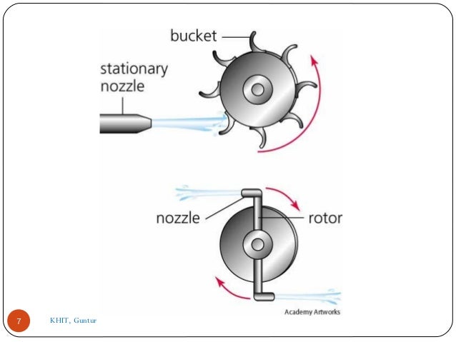
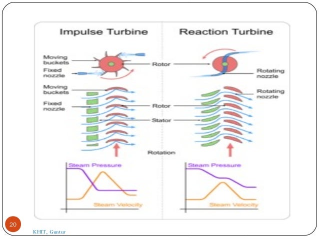
In one type of turbine, the rotating blades are shaped like buckets. High-velocity jets of incoming steam from carefully shaped nozzles kick into the buckets, pushing them around with a series of impulses, and bouncing off to the other side at a similar speed but much-reduced pressure (compared to the incoming jet). This design is called an impulse turbine and it's particularly good at extracting energy from high-pressure steam. (The de Laval turbine illustrated up above is an example.)
In an alternative design called a reaction turbine, there's a second set of stationary blades attached to the inside of the turbine case. These help to speed up and direct the steam onto the rotating blades at just the right angle, before it leaves with reduced temperature and pressure but broadly the same speed as it had when it entered.
In both cases, steam expands and gives up some of its energy as it passes through the turbine. In an ideal world, all the heat and kinetic energy lost by the steam would be gained by the turbine and converted into useful kinetic energy (making it spin around). But, of course, the turbine will heat up somewhat, some steam might leak out, and there are various other reasons why turbines (like all other machines) are never 100 percent efficient.
Disused Pelton water wheel. A reaction turbine
Photo: Impulse and reaction. Left: This Pelton water wheel is an example of an impulse turbine. It spins as high-pressure water jets fire into the buckets around the edge. Steam impulse turbines work a bit like this. Photo courtesy of Wonderferret, published on Flickr under a Creative Commons licence. See more of Wonderferret's photos. Right: A reaction turbine turns when steam hits its curved blades. Photo by Henry Price courtesy of US Department of Energy/National Renewable Energy Laboratory (DOE/NREL).

Other parts

Apart from the rotor and its blades, a turbine also needs some sort of steam inlet (usually a set of nozzles that direct steam onto either the stationary or rotating blades).
Steam turbines also need some form of control mechanism that regulates their speed, so they generate as much or as little power as needed at any particular time. Most steam turbines are in huge power plants driven by enormous furnaces and it's not easy to reduce the amount of heat they produce. On the other hand, the demand (load) on a power plant—how much electricity it needs to make—can vary dramatically and relatively quickly. So steam turbines need to cope with fluctuating output even though their steam input may be relatively constant. The simplest way to regulate the speed is using valves that release some of the steam that would otherwise go through the turbine.

Steam turbine, Impulse and Reaction turbine working principle,Compounding of steam turbines

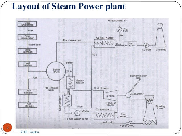
Layout of Steam Power plant
2
KHIT, Guntur
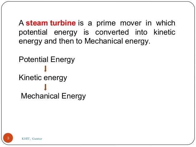
A steam turbine is  a  prime  mover  in  which 
potential  energy  is  converted  into  kinetic 
energy and then to Mechan...
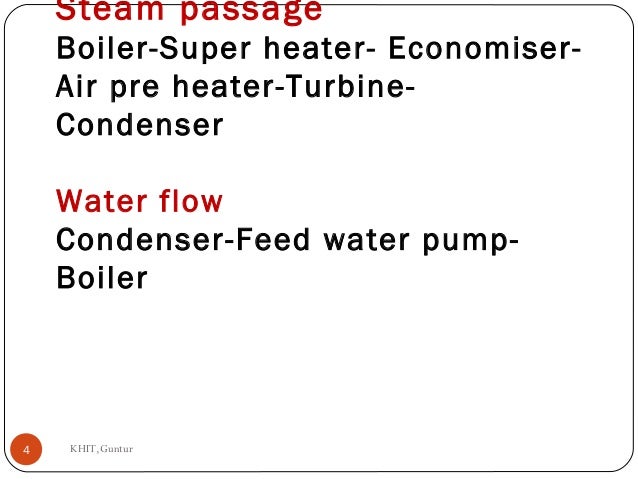
Steam passage
Boiler-Super heater- Economiser-
Air pre heater-Turbine-
Condenser
Water flow
Condenser-Feed water pump-
Boi...
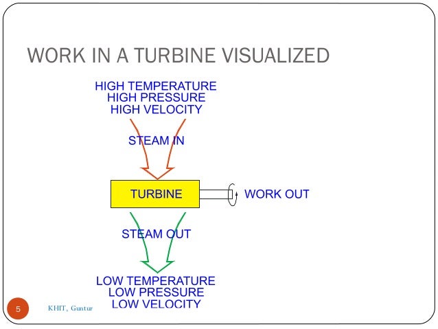
WORK IN A TURBINE VISUALIZED
5 KHIT, Guntur
Description of common types of Turbines.
1. Impulse Turbine.
2. Reaction Turbine.
The  main  difference  between  these  t...
7 KHIT, Guntur
In the impulse turbine, the steam expands 
in  the  nozzles  and  it's  pressure  does  not 
alter as it moves over the bl...
PRESSURE-VELOCITY DIAGRAM FOR A
TURBINE NOZZLE
9
ENTRANCE
HIGH THERMAL ENERGY
HIGH PRESSURE
LOW VELOCITY
STEAM INLET
EXIT
...
Simple impulse Turbine.
It the impulse turbine, the steam
expanded within the nozzle and there is no any
change in the ste...
IMPULSE TURBINE PRINCIPLE
11
NOZZLE
STEAM
CHEST
ROTOR
KHIT, Guntur
12
PRESSURE-VELOCITY DIAGRAM FOR
A MOVING IMPULSE BLADE
13
VELOCITY
PRESSURE
TURBINE
SHAFT
DIRECTION OF SPIN
ENTRANCE
HIGH VE...
Reaction Turbine
In this type of turbine, there is a
gradual pressure drop and takes place
continuously over the fixed and...
The fixed blades act as a nozzle which
are attached inside the cylinder and the
moving blades are fixed with the rotor as
...
Because of the pressure drops in each
stage, the number of stages required in a
reaction turbine is much greater than in a...
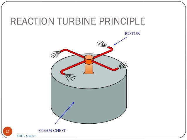
REACTION TURBINE PRINCIPLE
17 STEAM CHEST
ROTOR
KHIT, Guntur
18 KHIT, Guntur

PRESSURE-VELOCITY DIAGRAM FOR
A MOVING REACTION BLADE
19
TURBINE
SHAFT
DIRECTION OF SPIN
ENTRANCE
HIGH PRESSURE
HIGH VELOC...
20
KHIT, Guntur
21
.Compounding in Steam Turbine.
The compounding is the way of
reducing the wheel or rotor speed of the
turbine to optimum v...
Velocity Compounding:
There are number of moving blades separated by
rings of fixed blades as shown in the figure. All the...
24
Velocity Compounding
KHIT, Guntur
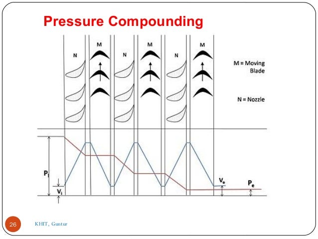
Pressure Compounding:
These are the rings of moving blades which are
keyed on a same shaft in series, are separated by
the...
26
Pressure Compounding
KHIT, Guntur
Pressure velocity compounding:
This method of compounding is the combination of two
previously discussed methods. The tota...

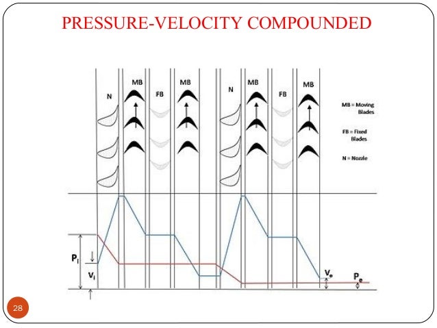
PRESSURE-VELOCITY COMPOUNDED
28
29
Reaction turbine pressure compounding
KHIT, Guntur
  1. 2. Layout of Steam Power plant 2 KHIT, Guntur
  2. 3. A steam turbine is  a  prime  mover  in  which  potential  energy  is  converted  into  kinetic  energy and then to Mechanical energy. Potential Energy Kinetic energy  Mechanical Energy 3 KHIT, Guntur
  3. 4. Steam passage Boiler-Super heater- Economiser- Air pre heater-Turbine- Condenser Water flow Condenser-Feed water pump- Boiler KHIT,Guntur4
  4. 5. WORK IN A TURBINE VISUALIZED 5 KHIT, Guntur
  5. 6. Description of common types of Turbines. 1. Impulse Turbine. 2. Reaction Turbine. The  main  difference  between  these  two  turbines  lies  in  the  way  of  expanding  the  steam while it moves through them.  6 KHIT, Guntur
  6. 7. 7 KHIT, Guntur
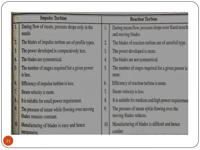
  7. 8. In the impulse turbine, the steam expands  in  the  nozzles  and  it's  pressure  does  not  alter as it moves over the blades.  In  the  reaction  turbine  the  steam  expanded  continuously  as  it  passes  over  the blades and thus there is gradually fall in  the  pressure  during  expansion  below  the  atmospheric pressure.  8
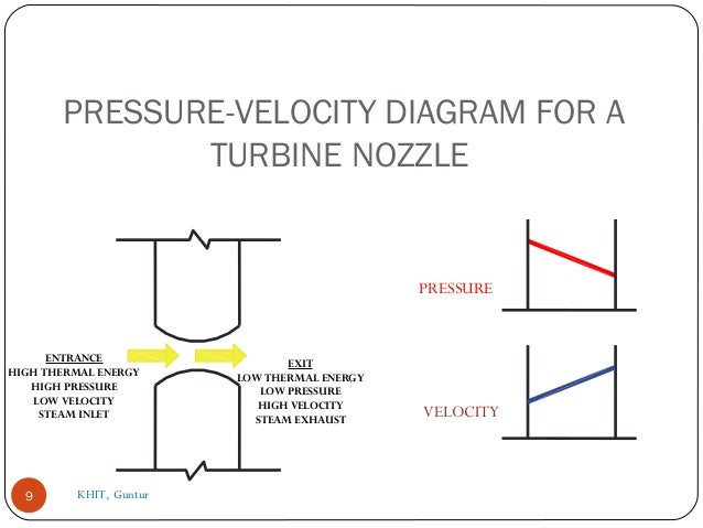
  8. 9. PRESSURE-VELOCITY DIAGRAM FOR A TURBINE NOZZLE 9 ENTRANCE HIGH THERMAL ENERGY HIGH PRESSURE LOW VELOCITY STEAM INLET EXIT LOW THERMAL ENERGY LOW PRESSURE HIGH VELOCITY STEAM EXHAUST PRESSURE VELOCITY KHIT, Guntur
  9. 10. Simple impulse Turbine. It the impulse turbine, the steam expanded within the nozzle and there is no any change in the steam pressure as it passes over the blades 10 KHIT, Guntur
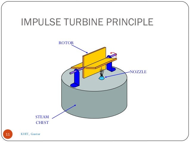
  10. 11. IMPULSE TURBINE PRINCIPLE 11 NOZZLE STEAM CHEST ROTOR KHIT, Guntur
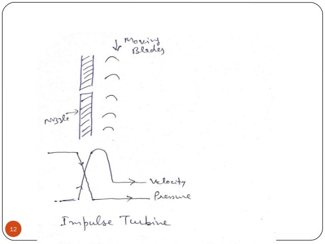
  11. 12. 12
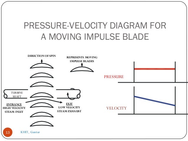
  12. 13. PRESSURE-VELOCITY DIAGRAM FOR A MOVING IMPULSE BLADE 13 VELOCITY PRESSURE TURBINE SHAFT DIRECTION OF SPIN ENTRANCE HIGH VELOCITY STEAM INLET REPRESENTS MOVING IMPULSE BLADES EXIT LOW VELOCITY STEAM EXHAUST KHIT, Guntur
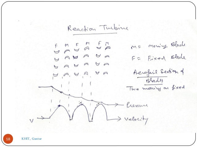
  13. 14. Reaction Turbine In this type of turbine, there is a gradual pressure drop and takes place continuously over the fixed and moving blades. The rotation of the shaft and drum, which carrying the blades is the result of both impulse and reactive force in the steam. The reaction turbine consist of a row of stationary blades and the following row of moving blades 14
  14. 15. The fixed blades act as a nozzle which are attached inside the cylinder and the moving blades are fixed with the rotor as shown in figure When the steam expands over the blades there is gradual increase in volume and decrease in pressure. But the velocity decrease in the moving blades and increases in fixed blades with change of direction. 15 KHIT, Guntur
  15. 16. Because of the pressure drops in each stage, the number of stages required in a reaction turbine is much greater than in a impulse turbine of same capacity. It also concluded that as the volume of steam increases at lower pressures therefore the diameter of the turbine must increase after each group of blade rings. PES16
  16. 17. REACTION TURBINE PRINCIPLE 17 STEAM CHEST ROTOR KHIT, Guntur
  17. 18. 18 KHIT, Guntur
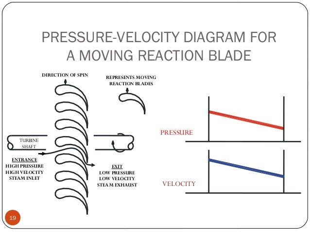
  18. 19. PRESSURE-VELOCITY DIAGRAM FOR A MOVING REACTION BLADE 19 TURBINE SHAFT DIRECTION OF SPIN ENTRANCE HIGH PRESSURE HIGH VELOCITY STEAM INLET REPRESENTS MOVING REACTION BLADES EXIT LOW PRESSURE LOW VELOCITY STEAM EXHAUST PRESSURE VELOCITY
  19. 20. 20 KHIT, Guntur
  20. 21. 21
  21. 22. .Compounding in Steam Turbine. The compounding is the way of reducing the wheel or rotor speed of the turbine to optimum value. Different methods of compounding are: 1.Velocity Compounding 2.Pressure Compounding 3.Pressure Velocity Compounding. In a Reaction turbine compounding can be achieved only by Pressure compounding.22 KHIT, Guntur
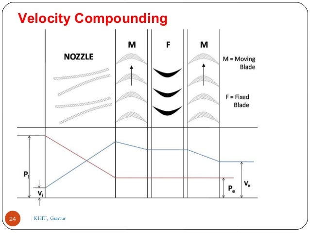
  22. 23. Velocity Compounding: There are number of moving blades separated by rings of fixed blades as shown in the figure. All the moving blades are keyed on a common shaft. When the steam passed through the nozzles where it is expanded to condenser pressure. It's Velocity becomes very high. This high velocity steam then passes through a series of moving and fixed blades. When the steam passes over the moving blades it's velocity decreases. The function of the fixed blades is to re-direct the steam flow without altering it's velocity to the following next row moving blades where a work is done on them and steam leaves the turbine with allow velocity as shown in diagram.23
  23. 24. 24 Velocity Compounding KHIT, Guntur
  24. 25. Pressure Compounding: These are the rings of moving blades which are keyed on a same shaft in series, are separated by the rings of fixed nozzles. The steam at boiler pressure enters the first set of nozzles and expanded partially. The kinetic energy of the steam thus obtained is absorbed by moving blades. The steam is then expanded partially in second set of nozzles where it's pressure again falls and the velocity increase the kinetic energy so obtained is absorbed by second ring of moving blades. 25
  25. 26. 26 Pressure Compounding KHIT, Guntur
  26. 27. Pressure velocity compounding: This method of compounding is the combination of two previously discussed methods. The total drop in steam pressure is divided into stages and the velocity obtained in each stage is also compounded. The rings of nozzles are fixed at the beginning of each stage and pressure remains constant during each stage as shown in figure. The turbine employing this method of compounding may be said to combine many of the advantages of both pressure and velocity staging By allowing a bigger pressure drop in each stage, less number stages are necessary and hence a shorter turbine will be obtained for a given pressure drop. 27
  27. 28. PRESSURE-VELOCITY COMPOUNDED 28
  28. 29. 29 Reaction turbine pressure compounding KHIT, Guntur

Effects of nozzle friction

Effects of nozzle friction

Friction losses in a nozzle depend upon various aspects. The effects of nozzle friction are as follows:

1. Reduction in enthalpy drop: Friction in nozzle affects its efficiency. As the efficiency of nozzle is the ratio of actual enthalpy drop to ideal enthalpy drop in nozzle, the friction in nozzle decreases the enthalpy drop.

2. Reduction in exit velocity: The kinetic energy of the steam increases at the expense of its pressure energy in the steam nozzle. Some kinetic energy gets lost to overcome the friction in nozzle. Therefore, exit velocity of steam decreases due to nozzle friction.

3. Increase in specific volume: Specific volume of steam can be defined as the of volume of steam per unit weight of the steam. Specific volume increases due to nozzle friction. 

4. Decrease in mass flow rate: As the friction in nozzle slows down the flow of steam in it, the mass flow rate also decreases due to nozzle friction.

Steam Turbines Classification

Turbine Classification

In order to better understand turbine operation, five basic classifications are discussed. Type of compounding refers to the use of blading which causes a series of pressure drops, a series of velocity drops, or a combination of the two. Division of steam flow indicates whether the steam flows in just one direction or if it flows in more than one direction. Type of steam flow describes the flow of steam in relation to the axis of the rotor. Exhausting condition is determined by whether the turbine exhausts into its own condenser or whether it exhausts into another piping system. Type of blading identifies the blading as either impulse blading or reaction blading.


High pressure turbine: The high pressure (HP) turbine (see Figure 1) is the first main engine turbine to receive steam from the main steam system. It is designed to efficiently extract work out of high pressure steam. The HP turbine is a pressure-velocity compounded, single axial flow, non-condensing impulse turbine.
  1. Type of compounding: Pressure-velocity describes the type of compounding. This refers to the use of blading which causes a series of pressure drops and a series of velocity drops.
  2. Type and division of steam flow: Single axial flow simply means the steam flows in only one direction parallel to the axis of the turbine rotor. Steam enters the forward end of the turbine and exhausts through the after end of the turbine. On a dual flow turbine the steam enters in the center of the turbine rotor and flows both forward and aft simultaneously.
  3. Exhausting condition: The HP turbine exhausts into the crossover pipe which directs the steam into the low pressure turbine. This exhausting condition causes the HP turbine to be a non-condensing turbine.
  4. Type of blading: The type of blading used on the HP turbine is impulse blading because it extracts more work from the high pressure steam than reaction blading. Impulse blading is in the shape of a half moon. As steam impacts the moving blade, it pushes the blade forward. This impact causes the steam to lose velocity without losing pressure. In order to efficiently extract the maximum amount of work out of the steam, two different types of impulse stages are used. The Curtis stage is the first stage of the HP turbine. The Curtis stage is designed to initially extract a large amount of work out of the steam as it enters the turbine. The remaining stages of the HP turbine are Rateau stages
    1. The Curtis stage (see Figure 2) is designed to be a power rotor, extracting a large amount of energy out of the steam. As main steam enters the HP turbine, it first passes through the nozzle block. The nozzle block contains the nozzles. The velocity of steam is increased and the pressure is decreased as the steam passes through these nozzles. On an impulse turbine, the only time a pressure drop occurs is when steam passes through a nozzle. After steam passes through the nozzles, it passes through the first set of moving blades. In the first set of moving blades, work is extracted from the steam causing the velocity to drop. After passing through the moving blades, the steam then passes through the non-moving blades. The only purpose the non-moving blades serve is to redirect steam from the first set of moving blades to the second set of moving blades. On an impulse turbine, non-moving blades do not have any effect on the pressure or the velocity of the steam passing through them. After leaving the non-moving blades the steam passes through another set of moving blades. This setup of a nozzle followed by a set of moving blades, non-moving blades, and moving blades makes up a single Curtis stage. After steam exits the nozzle there are no further pressure drops. However, across both sets of moving blades there is a velocity drop. This causes the Curtis stage to be classified as velocity compounded blading.

    1. The remaining stages of the HP turbine are a series of Rateau stages . A single Rateau stage consists of a nozzle diaphragm followed by a row of moving blades. The nozzle diaphragm separates the stages of an impulse turbine and provides support for the nozzles. The nozzles within the nozzle diaphragm serve the same purpose as the nozzles within the nozzle block. As steam passes through the nozzle, velocity is increased and pressure is decreased. After leaving the nozzle, steam then enters the moving blades where once again work is extracted from the steam. As work is extracted from the steam, its velocity will once again decrease even though its pressure will not be effected. Even though there is a velocity increase and a velocity decrease in each Rateau stage, the overall velocity from the inlet of the first Rateau stage to the exhaust of the final Rateau stage is not changed. In contrast, there is a pressure drop in each Rateau stage, resulting in an overall pressure drop from the inlet of the first Rateau stage to the exhaust of the final Rateau stage. This overall pressure drop causes the Rateau staging to be considered pressure compounded.
  
    1. There are various other components of the HP turbine which must be considered.


      Figure 5
      1. Foundation: The aft end of the HP turbine is rigidly mounted to the frame of the ship. The forward end is mounted using either sliding feet (similar to what is used on the boiler) or using a flexible I-beam (see Figure 5). The mounting is designed to support the weight of the forward end of the HP turbine as well as compensate for the expansion and contraction encountered during start up and securing.
      2. Steam chest: The steam chest, located on the forward, upper half of the HP turbine casing, houses the throttle valve assembly. This is the area of the turbine where main steam first enters the main engine. The throttle valve assembly regulates the amount of steam entering the turbine. After passing through the throttle valve, steam enters the nozzle block.
    2. Turbine casing drains remove the condensate from the turbine casing during warm-up, securing, maneuvering and other low flow conditions.
  
  1. Low pressure (LP) turbine: The LP turbine (see Figure 6) is located next to the HP turbine. The LP turbine is a pressure compounded, either single or dual axial flow, condensing reaction turbine.
     
    1. Division of steam flow: On ships where space is a consideration, the LP turbine is designed to be a dual flow turbine. Steam enters the center of the turbine from the crossover pipe and flows across the reaction blading in two opposite directions. This configuration reduces axial thrust on the turbine and allows for a smaller turbine installation. On ships where space is not a concern, a single flow turbine is used.
    2. Direction of steam flow: Just like on the HP turbine, steam flows parallel to the turbine rotor.
    3. Exhausting condition: Unlike the HP turbine, the LP turbine exhausts into the main condenser. Because the LP turbine exhausts into its own dedicated condenser, it is considered a condensing turbine.

      Figure 6
       
    4. Type of blading: The major difference between the HP turbine and the LP turbine is the type of blading used. Because the steam entering the HP turbine is at a high pressure it is more efficient to use impulse blading. The steam entering the LP turbine is at a significantly lower pressure than the steam entering the HP turbine. In order to efficiently extract work out of this lower pressure steam, reaction blading is used on the LP turbine. Reaction blading works on the same concept as a jet engine. A jet engine is designed to take in air, compress it, heat it up and discharge it through the back. As the air exits the jet engine, it expands, pushing the jet engine forward. As the jet engine is pushed forward, it propels the jet through the air. Similarly, each moving reaction blade, is designed to act as a nozzle (miniature jet engine). As the steam passes through a reaction blade it causes the reaction blade to be propelled forward, resulting in rotation of the LP turbine rotor. Both the moving blades and the non-moving blades of a reaction turbine are designed to act like nozzles. As steam passes through the non-moving blades, no work is extracted. Pressure will decrease and velocity will increase as steam passes through these non-moving blades. In the moving blades work is extracted. Even though the moving blades are designed to act like nozzles, velocity and pressure will decrease due to work being extracted from the steam.
    5. Type of compounding: Due to the overall effect being a loss of pressure across the LP turbine blading, the LP turbine is a pressure compounded turbine.
  1. Astern turbine: The astern turbine is designed to propel the ship in the astern direction. The concept is the same as in a car. A car is designed to go both forward and reverse. The designers could have designed the car with two totally separate transmissions, one for forward and one for reverse. Instead, they designed cars with one transmission capable of going both forward and reverse. The same concept exists on the ship's main engines. The ship is not designed with two engines per shaft. Rather, it is designed with one engine per shaft. In a car, the ability to go in reverse is contained within the transmission. On the ship's main engine, the ability to go astern is contained within the LP turbine. The astern turbine is designed as an integral part of the LP turbine rotor. On a double flow LP turbine, the ahead elements of the LP turbine are located towards the center of the LP turbine. The astern elements are located on the forward and after end of the LP turbine rotor. On a single flow LP turbine, the astern elements are located on the forward end of the LP turbine. The astern turbine is a single axial flow, velocity compounded, condensing impulse turbine consisting of one or two Curtis stages located on the forward and/or after end of the LP turbine.
     
  2. Other Components
    1. Deflector plate: During astern operations the steam will naturally want to flow into the ahead elements of the LP turbine. Similarly, during ahead operations the steam will naturally want to flow into the astern elements of the LP turbine. If this were permitted, the rotation created by the ahead elements would be hindered by the steam acting on the astern elements. To prevent this, a deflector plate is installed. This deflector plate provides a physical barrier to prevent steam from the ahead elements from impinging on the astern elements and vice versa.
    2. Sentinel valves: There are two sentinel valves installed on the LP turbine. One sentinel valve is located on the crossover pipe leading to the LP turbine and the second is located on the forward end of the LP turbine casing. Both of these sentinel valves warn the operator of over-pressurization of the LP turbine. A sentinel valve does not relieve system pressure. It only acts to provide an audible alarm in the event of overpressurization of the LP turbine. Some crossover pipes also have relief valves installed.
    3. Bearings: In order to support the weight of the turbine and to maintain radial and axial alignment, two different types of bearings are used.
      1. Turbine journal bearings maintain the radial alignment of the turbine and supports the weight of the rotor. Bearings are spherically seated allowing for slight radial misalignment during installation only. They are located on the forward and after end of both turbine rotors.
      2. Turbine thrust bearings absorb any axial thrust created in the turbine and also maintain the axial position of the rotor in the casing. The thrust bearings are double acting, segmented shoe, Kingsbury type thrust bearings. They are usually located on the forward end of each turbine rotor.
    4. Flexible coupling: Transmits the torque from the turbines to the reduction gears. The flexible couplings are designed so that any thrust created in the turbines will not be transmitted to the reduction gears. They also allow for slight radial misalignment and provide a means of disconnecting the turbines from the main reduction gears.
  3. Monitoring of parameters: In order to operate the main engines safely, various parameters must be constantly monitored. These main engine indicators will give the operator an idea of the operating condition of the main engine.
    1. The rotor position indicator (RPI), Located on the forward end of the turbine rotor, this device indicates a safe distance between fixed and moving blades inside the turbine and gives indication of thrust bearing wear. As the thrust bearing naturally wears, this reading will gradually increase.
    2. HP turbine steam chest pressure: Indicates available steam pressure to the main engine from the boiler. This pressure gage senses the pressure of the steam entering the steam chest. The gage is located on the throttle board.
    3. First stage pressure: Measured at the point where steam is exhausting the first stage nozzle block. As the throttle valve is opened, admitting more steam to the turbine, this pressure will increase. As the throttle valve is shut this pressure will decrease. The gage is located on the throttle board. During speed changes, the throttle man controls the amount of steam admitted to the turbine. This gage allows the throttle man to monitor the amount of steam admitted to the engine.
    4. First stage temperature: Indicates the temperature of the first stage of the HP turbine. During astern operations, there is no flow of steam through the HP turbine to cool the turbine blading. However, due to the HP turbine being connected to the reduction gear, it will still rotate in the reverse direction. As the HP turbine blading passes through the air inside the turbine casing, friction is created. This is known as windage. During extended astern operations, windage will create large amounts of heat. If the turbine rotor overheats, damage will occur to the turbine blading and rotors. The watch standers monitor this temperature in order to be aware of any overheating which may be occurring. Windage also occurs on multi-shaft ships when a shaft is trailing.
    5. HP turbine exhaust pressure: Indicates the pressure of steam exhausting from the HP turbine before it enters the LP turbine. At low speeds, the vacuum of the main condenser may be pulling the steam through the turbines and this gage may indicate a vacuum.
    6. Main condenser vacuum: Indicates the vacuum (pressure below atmospheric pressure) in the main condenser. The main condenser is designed to operate under a vacuum. If a decrease in vacuum occurs, the main engine will no longer operator efficiently. If vacuum is totally lost, this could result in damage to the main engine. This low pressure area is the most efficient place for turbine exhaust steam.
    7. Main engine lube oil pressure: Indicates oil pressure at the most remote bearing. This is the bearing farthest away from the lube oil pump. In the event system pressure is lost, this bearing will normally be the first one to lose lube oil pressure.
    8. Bearing oil outlet thermometers: Give an indication of the temperature of the oil leaving the bearings. If a bearing overheats, the babbitt will begin to break down causing a bearing failure. By monitoring bearing temperature, a watch stander will notice any bearings which are abnormally hot and will be able to take corrective action in order to prevent any further bearing damage from occurring.
    9. Sight flow indicators (SFI) are located on the outlet of the bearing and allow the watch stander to monitor oil flow through a bearing. The SFI is constructed with small glass windows which permit the watch stander to look into the indicator. Normally a flow of oil can be seen through the SFI. In the event lubrication is lost to the bearing, the watch stander will not see a flow of oil through the SFI.

      NOTE: All bearings have both a sight flow indicator and a temperature gage attached to them. A watchstander monitoring the RPI�s, SFI�s and bearing oil temperature on main engines is conducting what is called a THREE POINT CHECK and can quickly report the satisfactory or unsatisfactory condition of the turbines.

  1. Steam flow: During normal ahead operations, main steam first enters the steam chest. The amount of steam then allowed to flow from the steam chest into the turbine is controlled by the throttle valve located in the bottom of the steam chest. After passing through the throttle valve, steam then passes through the nozzle block. The nozzle block causes the pressure of steam to drop while increasing steam velocity. The Curtis stage extracts work from the steam and sends the steam to the Rateau stages. After exhausting from the final Rateau stage, steam flows through the crossover pipe into the LP turbine. The reaction blading of the LP turbine extracts more work from the steam. After steam exhausts from the LP turbine blading, it flows through the exhaust trunk into the main condenser.
    1. During astern operations steam will not enter the steam chest of the HP turbine. Instead, after flowing through the main engine guarding valve, main steam is directed to the astern elements of the LP turbine located in the forward and after end of the LP turbine. After passing through the astern elements, steam then flows through the exhaust trunk and into the main condenser.
  1. Safety is of the utmost importance while operating the main engine. Failure to observe safety precautions can result in damage to the main engine, personnel injuries, or even death. Even though many safety precautions seem to be common sense, many times personnel fail to consider the results of their actions.
    1. Never place any part of the body near rotating machinery. While it is highly unlikely anyone will ever attempt to grab the main shaft while it is rotating at 200 rpm, there are other things to be considered. While the main engine jacking gear is engaged, the shaft is rotating at a very slow rate. Despite this slow rotation, watchstanders still should not be permitted to do any type of work to the main shaft, such as painting or cleaning the main shaft.
    2. Do not wear jewelry, neckties, or loose fitting clothing while operating equipment. This clothing can become entangled in the machinery and cause injury or death.
    3. Oil leaks shall be corrected at their source. Spills of any kind shall be wiped up immediately and the wiping rags disposed of immediately or stored in fire safe containers. Failure to observe safety with any petroleum product can result in a major Class B fire.
    4. Promptly reinstall shaft guards, coupling guards, deck plates, handrails, flange shields and other protective devices removed as interferences immediately after completion of maintenance on machinery, piping, valves or other system components.
    5. An open main engine presents special safety precautions. While the main engine is open, an E-5 or above is required to stand guard. A security area is established around the main engine using ropes and signs. No tools are permitted within the security area without first being inventoried by the guard. Before personnel are permitted to enter the security area, they are required to remove all jewelry, securely fasten eyeglasses and tools to their body using lanyards, and all clothing fasteners must be covered with tape. As an added safety precaution, ensure all warfare and rank devices are removed before entering the security area. This precaution prevents inadvertent introduction of anything that could cause damage to the turbines.

Steam Turbine

Principle of operation of steam turbine:

An ideal steam turbine is considered to undergo an isentropic process, or constant entropy process, in which the entropy of the inlet steam is equal to the entropy of the outlet steam in the turbine. No steam turbine is purely isentropic, however, with distinctive isentropic efficiencies of 20–90% on the basis of the application of the turbine. The inner side of a turbine is made up of several sets of blades/buckets. A set of stationary blades is fixed to the casing and a set of rotating blades is linked to the shaft. These sets intermesh with certain minimum clearance, with the size and configuration of sets changing to efficiently exploit the expansion of steam at each stage.

Types of steam turbines

Generally, the turbines are classified into two types,
  1. Impulse Turbine
  2. Reaction Turbine
    Fig 1. Impulse and Reaction turbine
Fig 1. Impulse and Reaction turbine
Impulse Turbines
In this type of turbine, the steam jets are directed at the turbine’s bucket shaped rotor blades so that the pressure exerted by the jets causes the rotor to rotate and there is a reduction in the velocity of the steam as it expenses its kinetic energy in rotating the blades. As a result blades change the direction of flow of the steam with its pressure remaining constant as it passes through the rotor blades meanwhile the cross section of the chamber between the blades is constant. So impulse turbines are also called as constant pressure turbines. The next series of the fixed blades reverses the direction of the steam and then it passes to the second row of moving blades.
Reaction Turbines
The rotor blades of the reaction turbine are shaped like airfoils, arranged in such a way that the cross-section of the chambers between the fixed blades lessens from the inlet side towards the outlet side of the blades. The chambers in between the rotor blades importantly form nozzles so that as the steam advances through the chambers its velocity rises but at the same time its pressure decreases, just as in the nozzles made up of the fixed blades. Thus, the pressure reduces in both blades; fixed and moving. As the steam arises in a jet from between the rotor blades, it forms a reactive force on the blades which then creates the turning moment on the turbine rotor, just like in Hero’s steam engine. [Newton’s Third Law – For every action there is an equal and opposite reaction]

Compounding of impulse turbine:

Compounding of impulse turbine is done to reduce the rotational speed of the impulse turbine to practical limits. (A rotor speed of 35,000 rpm is possible, but is very high for the practical uses.). Compounding is done by using more than one set of nozzles, blades, rotors, in a series, fixed to a common shaft; so that either the steam pressure or the jet velocity is utilized by the turbine in stages.
There are three main types of compounding done on impulse turbines. They are:
  1. Pressure compounding,
  2. velocity compounding and
  3. Pressure and velocity compounding impulse turbines.
  1. Velocity Compounding:
 Fig 2. Velocity Compounding
Fig 2. Velocity Compounding
Pi = Inlet Pressure, P= Exit Pressure, V= Inlet Velocity, and V= Exit Velocity
The idea of the velocity-compounded impulse turbine was first introduced by C.G. Curtis for solving the problems of a single-stage impulse turbine for the use with high pressure and temperature steam. So it is also called “The Curtis Stage Turbine”. The Curtis stage turbine is formed of 1 stage of nozzles as the single-stage turbine, followed by 2 rows of moving blades. These two rows of moving blades are separated by one row of fixed blades attached to the turbine stator, which redirects the steam exiting the first row of moving blades towards the second row of moving blades. A Curtis stage impulse turbine is shown in Fig. below with the schematic pressure and absolute steam-velocity changes through the stage. In the Curtis stage, the overall enthalpy drop. So, pressure drop occurs in the nozzles so that the pressure does not vary in all three rows of blades.
  1. Pressure Compounding:
Fig 3. Pressure Compounding
Pressure compounding involves dividing up of the whole pressure drop from the steam chest pressure to the condenser pressure into a series of smaller pressure drops across the several stages of impulse turbine. The nozzles are installed into a diaphragm locked in the casing. This diaphragm separates the wheel chamber from each other. All rotors are mounted on the same shaft and the blades are fixed on the rotor.
  1. Pressure-Velocity Compounding:
It is a combination of pressure compounding and velocity compounding.
Fig 4. Pressure-Velocity Compounding
Two-row velocity compounded turbine is found to be more efficient than the three-row type. In a two-step pressure velocity compounded turbine, at first pressure drop arises in the first set of nozzles, the resulting addition in the kinetic energy is absorbed successively in two rows of moving blades before the second pressure drop takes place in the second set of nozzles. As the K.E gained in each step is used up completely before the next pressure drop, the turbine is both pressure as well as velocity compounded. The kinetic energy added due to the second pressure drop in the second set of nozzles is taken up successively in the two rows of moving blades. This type of steam turbine is comparatively simple in construction and is very much compact than that of the pressure compounded turbine.
Fig 5(a). Velocity triangle of impulse turbine
Fig 5(a),(b). Velocity triangle of impulse turbine
The fixed blades guide the outlet steam from the previous stage in such a way so as to smoothen the entry at the next stage is ensured. K, the blade velocity coefficient may be different in each row of blades.

Reaction Turbine:

A reaction turbine consists of rows of fixed and rows of moving blades. The fixed blades function as nozzles. The moving blades get motion as a result of the impulse of steam received and also due to expansion and acceleration of the steam relative to them i.e. they also act as nozzles. The drop in enthalpy per stage of one row fixed and one-row moving blades are shared among them, often equally. Thus, a blade having 50 % degree of reaction is the one in which half of the total enthalpy of the stage drops in the fixed blades and the half in the moving blades. But the pressure drops will not be equal. They are larger for the fixed blades and larger for the high-pressure than the low-pressure stages. The moving blades of a reaction turbine can be easily distinguished from those of an impulse turbine because they are not symmetrical and, also because they act partly as nozzles, have a shape similar to that of the fixed blades, but curved in the opposite direction. The schematic pressure line in the figure given below shows that pressure drops continuously through all rows of blades, fixed and moving. The absolute steam velocity varies within each stage as shown and keeps repeating from stage to stage. The second figure shows the velocity diagram for the reaction stage.
Fig 6. Compounded Reaction Turbine
 Fig 7. Velocity triangle for Reaction Turbine
Fig 7. Velocity triangle for Reaction Turbine
A very widely used design has half a degree of reaction or 50% reaction and this is known as Parson’s Turbine. This consists of a symmetrical stator and rotor blades. The velocity triangles are symmetrical and we have,

Things to rememer

  • Generally the turbines are classified into two types,
    1. Impulse Turbine
    2. Reaction Turbine
  • In impulse steam turbine, the steam jets are directed at the turbine’s bucket shaped rotor blades so that the pressure exerted by the jets causes the rotor to rotate and there is reduction in the velocity of the steam as it expenses its kinetic energy in rotating the blades.
  • The rotor blades of the reaction turbine are shaped like airfoils, arranged in such a way that the cross section of the chambers between the fixed blades lessens from the inlet side towards the outlet side of the blades.
  • There are three main types of compounding done on impulse turbines. They are:
    1. Pressure compounding,
    2. velocity compounding and
    3. Pressure and velocity compounding impulse turbines.
  • A reaction turbine consists of rows of fixed and rows of moving blades. The fixed blades functions as nozzles. The moving blades get motion as a result of the impulse of steam received and also due to expansion and acceleration of the steam relative to them.
  • A very widely used design has half degree of reaction or 50% reaction and this is known as Parson’s Turbine. This consists of symmetrical stator and rotor blades.